The Accelerometer

The accelerometer is one of the the five sensor types on the Micromelon Rover. The accelerometer is a component built into the Rover’s PCB (printed circuit board). It’s only about a 2.5mm x 3.0mm wide and 0.83mm tall. That component also includes another sensor, the gyroscope.
What Does It Do?
The accelerometer is a device designed to detect the acceleration caused by forces acting on the rover (which we’ll dig into a bit more later). The accelerometer is a great tool for figuring out the rovers orientation in the world. Think of it as the primary tool for the Rover’s sense of balance.
Important Concepts
Before we get into the mechanics of an accelerometer, we need to cover some physics concepts.
Acceleration
Acceleration is the change in velocity of an object. For example when you go from a walk to a run, you are accelerating by using the forces you generate with your muscles. As you slow down, you decrease your acceleration. All movement has a rate of acceleration. Whenever our rovers are moved, either by a force like gravity or the rotation of their motors, that movement also have a rate of acceleration.
Forces
When we push our rover, we are applying a force to it. When that force is unopposed the rover will be in motion. Anything that can apply motion to the Rover and change its position in space is considered a force. We can organize all forces into two categories, static forces & dynamic forces.
Dynamic Force
Dynamic forces can change. When we pick up and move our rover, our hand moves at an unpredictable and changing rate, so the force applied to the rover is dynamic.
Static Force
Static forces do not change. The best example of a static force is gravity. Our rover will always be affected by gravity, as are all objects on earth.
Now that we have covered those things, it’s time to jump into how the accelerometer works.
How Does An Accelerometer Work?
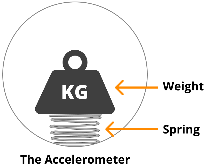
The accelerometer on the Rover is a MEMS accelerometer. MEMS stands for microelectromechanical systems. There is a lot of marvellous engineering in MEMS however they are complicated devices that we won’t go into in this post. To simplify things for this post, just imagine that inside the accelerometer there is a spring with a weight attached to it. This weight moves around when there is a force applied to it. As the weight moves, the spring will contract, expand, and tilt.
Depending on how the spring contracts, expands, and tilts, the accelerometer can measure acceleration.
Simplified Accelerometer Example

Let’s walk through an example where the outside force is gravity.
When no force is applied, the spring is sitting in it’s default position.
As gravity is applied, the weight is pulled down and the spring compresses under it.
When the rover is flipped upside down, the accelerometer is as well. The weight is still pulled down by gravity but now the spring is extending.
When the spring compresses & extends, the accelerometer can detect there is force being applied to the rover.
So we have a rough idea of how the accelerometer is able to determine that force is being applied. Let’s talk now about how it communicates to us where the force is coming from.
The 3 Axes Of Movement
With the accelerometer, our Rover can detect its acceleration, but it needs a way to communicate it. It would be a bit confusing if our Rover told us “hey I’m accelerating down but I’m upside down so I’m moving in this direction but also accelerating to the side as well to my right, your left…”. This is a bit confusing. We need a simple way for us to understand and communicate the rover’s direction of motion. This is what the axes of movement are for.

The X, Y, and Z axes
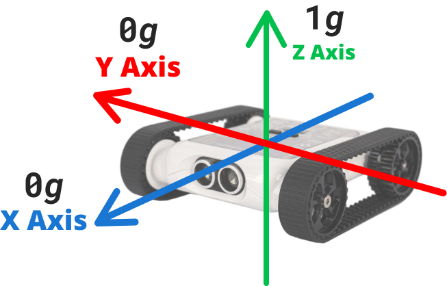
The X axis runs from back to front of the rover. The Y axis runs across the rover middle from left to right. The Z axis runs up and down through the rover.
As the rover moves, these axis stay localized to the rover. So as the rover rotates, the axis rotate with it. You can see where the 3 Axes are on the rover and how they move when it rotates.
The 3 Axes In the Accelerometer
Let’s look back at our weight and spring example and apply the 3 axis of movement to it. Remember, the 3 axis are localized to the rover. As the Rover rotates, the axis rotate as well.

The force of gravity is applied downwards on the Rover as it sits flat. The accelerometer detects force of gravity against the Z axis.

When the rover flips over the force is still applying downwards but to the Rover’s underside. The accelerometer detects force of gravity going with the Z axis.
Bringing It All Together
The accelerometer is a device built into the Rover. As forces like gravity, our hands, or the rover’s own motors move the rover, the accelerometer mechanisms move and shift around. The accelerometer monitors this moving and shifting and then calculates which of the 3 axis is affected by the outside forces. We can then read this data and program the Rover to respond to outside forces being applied.
Does Nature Have Accelerometers?
Similar to how the Rover may use the accelerometer to help balance itself, humans also have a form of accelerometer we use to balance. Our accelerometer is in our ear, specifically a part of our ear called the inner ear.
How the Inner Ear Helps Us Balance
The inner ear has a lot of parts, not all of them are to help us balance. Three parts that do help us balance are the three semicircular canals. These are named the posterial, anterior & lateral canals.
Inside these canals are tiny hairs and liquid. As we move our head the liquid inside the canals shifts back and forth. The tiny hairs detect the liquid moving and send signals to our brain.
Our Rover’s accelerometer is designed to understand movement along 3 axes. Our inner ear does the same, each semicircular canal is responsible for an axis. The Lateral canal is for our Z axis, the Anterior for our Y axis and the Posterior for the X axis.

Diagram of the ear

Diagram of the inner ear
Programming The Accelerometer
Open up the Code Editor, connect to a Micromelon Rover and open up the sensor view. To open sensor view, click the ROVER button next to your rover’s name.
In the sensor view dialog, the accelerometer values are located in the bottom right table. The first column of the table is the accelerometer values. Move the rover around and take note of how the X, Y and Z values change.

Understanding Accelerometer Values
The values you see in the accelerometer column are g-force values. G-force ( g ) is a standard unit of measurement for force. 1g equals the same amount of force applied by Earth’s gravity. When a Rover is in free-fall, with no external forces, it will read 0g in all axes.
Demonstrating G-Force
Rest the rover up right on a flat surface, you will see both the X and Y value are roughly 0g, however the Z value will be roughly 1g. The only force applied to the rover is Earth’s gravity, pushing down on the Z-axis.

If you flip the rover upside down, X and Y will still be roughly 0g. The Z axis will be equal to roughly -1g. This is because Earth’s gravity is now going the other way on the Z axis.
Beyond 1 G-Force
Most of the time while using your rover, you will only see accelerometer readings between -1 and 1. The accelerometer is configured to track up to (+/-)2 g-force (the easiest way to see this is to lift your rover up against gravity). In normal use, your rover will have to be moving fairly fast to reach those high values. Remember, the old Micromelon saying…It’s not the speed that breaks your rover, it’s the sudden stop that will.
Using The Accelerometer In Code
Let’s write a simple program to change our Rover’s LEDs depending on the value of the z axis of our accelerometer.
Start by adding an IF/ELSE block.
Inside the condition, place a Read X Axis From Accelerometer block. You can find this in the Sensors category.
Change the X Axis dropdown to Z Axis.
The python command for reading the Z axis is IMU.readAccel(2)
Change the second value on the < condition block from 10 to 0. This will check if the value is either positive or negative.
Inside the IF/ELSE block true case, place an Set All LEDs block. You can find this in the Lights/Sound category.
Inside the IF/Else block false case, place another Set All LEDs block but set it to a different colour.
Place the whole IF/ELSE block in a While True loop.
Press Play!
While this code is running, we will see the Rover LEDs change to our selected colours depending on if it is right way up or upside down. Flip the rover over to test if it works!
Wrapping Up
Now that we’re familiar with what the accelerometer is, how it works, and how to program it, it’s time to start doing some activities. Try these activities that require using the accelerometer.


Related Posts


