The Gyroscope
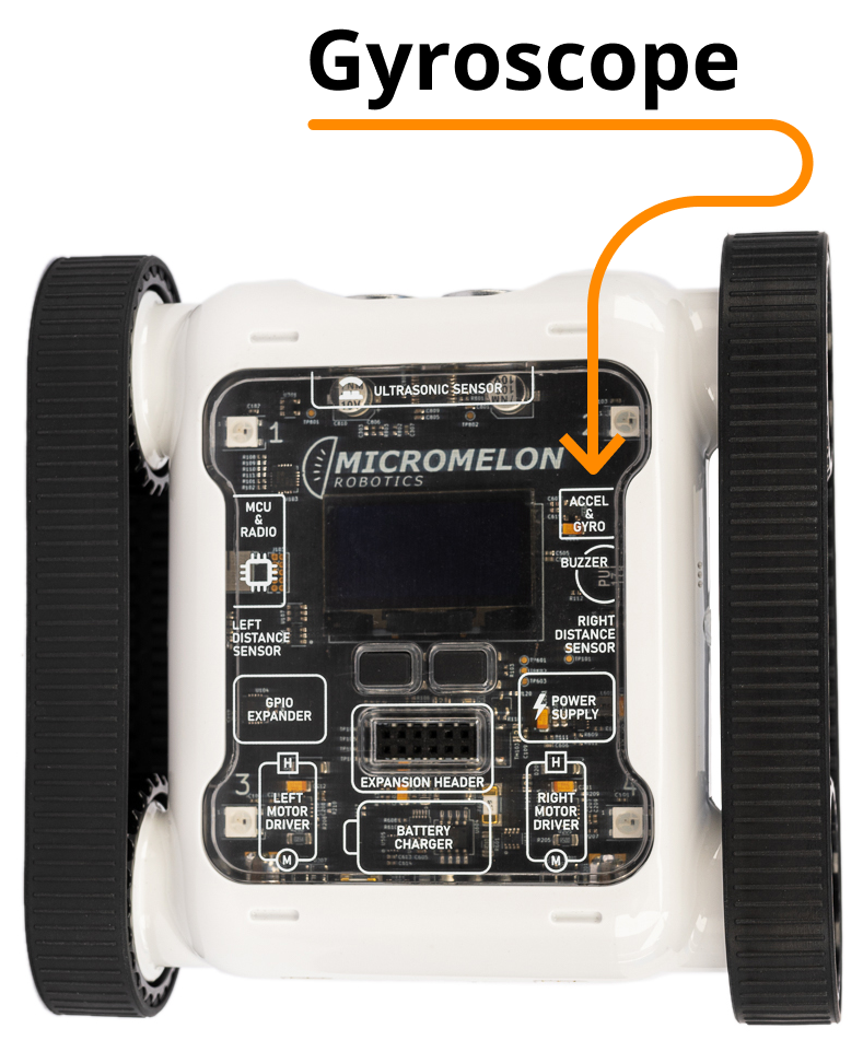
The gyroscope is one of the five sensor types on the Micromelon Rover. The gyroscope is a component built into the Rover’s PCB (printed circuit board). It’s only about 2.5mm x 3.0mm wide and 0.83mm tall. This component also includes another sensor, the accelerometer.
What Does It Do?
The gyroscope is a device designed to detect how fast the rover is rotating and in what direction it is rotating. The gyroscope is a great tool understanding the Rover’s rotational movement in space. Think of it as a key tool for the Rover’s sense of direction.
History of the Gyroscope

A Traditional Gyroscope
Gyroscopes have existed long before digital devices like the Rover used them. Gyroscopes have been used as tools since the 1800’s. The gyroscopes used back then were devices built out of metal loops called gimbal rings that can spin freely, attached to a central piece called the rotor. You can see a diagram of a traditional mechanical gyroscope to the right.
The spin axis & rotor are designed to spin at a height speed. As the spin axis & rotor are in motion, the attached gimbal rings rotate inside the gyroscope frame. How gyroscope movement works and why it’s so important is a bit hard to explain through text. Instead, let’s just see what happens when a gyroscope is & isn’t in motion.
In Motion
No Motion


Gyroscope footage above sourced from the YouTube channel ScienceOnline.
As we can see, when the gyroscope components are not in motion, gravity causes the gyroscope to fall over as expected. When the gyroscope’s components are spinning the gyroscope is able to remain stable seemingly against the force of gravity. This is due to a phenomenon called angular momentum. While the gyroscope spin axis & rotor are spinning fast enough the angular momentum will be maintained and the gyroscope will maintain its vertical position against the force of gravity.
How Does The Rover Gyroscope Work?
The gyroscope on the Rover is something called a microelectromechanical system (MEMS). A MEMS gyroscope mechanically works a lot different to a traditional mechanical gyroscope like the one’s we’ve seen already. It doesn’t have a spinning rotor and gimbal rings. Although a traditional gyroscope and a MEMS gyroscope mechanically work different, the fundamental physics is the same. There is a lot of marvellous engineering that go into MEMS gyroscopes. We won’t explain that here as it’s a bit too complicated for one blog post.

To simplify things, let’s imagine inside the rover there is a traditional mechanical gyroscope that is constantly in motion (so it will always stay straight even against gravity). Around the gyroscope is a protractor. When the rover is flat on the ground, the the protractor aligns the gyroscope with 0 degrees. Let’s breakdown how this helps our rover determine rotation.

The rover starts flat. The 0th degree of the protractor is aligned with the gyroscope. This means there is no rotation.
As the Rover rotates, the protractor rotates with it. The gyroscope remains stable and straight.
When the Rover stops rotation, the gyroscope now points at a different degree of the protractor.
The Rover determines degrees of rotation based on how the protractor rotates around the gyroscope.
In our example we can see the rover rotating on its side. The rover could also roll backwards & forwards or spin on the spot. It starts to get a bit complicated when we add all of these together. We need a simple way to understand rotation. That’s what the 3 axis of movement are for.
The 3 Axis of Movement
Using the gyroscope, our Rover can detect it is rotating but it can also tell us specifically in which direction it is rotating. It doesn’t make sense if the rover starts telling us “Hey I am spinning left”. Unfortunately, this isn’t clear enough. We need a simple way for us to understand and communicate the Rovers direction of rotation. This is what the 3 axis of movement are for.

The 3 Axis, X Y and Z
The 3 axis are specific directions the rover uses. The X axis runs from back to front of the rover. The Y axis runs across the rover middle from left to right. The Z axis down and up through the Rover’s middle.
The rover can rotate around all 3 axis. Below is a demonstration of rotation along each axis.
X Axis Rotation

Y Axis Rotation

Z Axis Rotation

Gyroscope Calibration
Although the Rover’s gyroscope is reliable at detecting rotation changes consistently it won’t always be perfect to the exact degree. Even when the rover is in a completely stationary position, the gyroscope may say that it is detecting the slightest amount of rotation happening even though there is no rotation. This difference between the gyroscope values and the real rotation is so small that in 99% of circumstances it will be inconsequential when programming.
This irregularity is unfortunately unavoidable for the Rover’s built in gyroscope. You can always re-calibrate the Rover’s sensors if you want to make sure they are as accurate as possible.
How To Recalibrate the Gyroscope

Open the Code Editor and connect to the Rover you want to calibrate. If you need a refresher on using the Code Editor, check out the Getting Started With The Micromelon Rover post
In the Code Editor’s program menu, click the Rover button to open the dropdown.
Select the Sensor Calibration option.
As the sensor calibration dialog instructs, place the rover on the most level surface possible.
Press Calibrate
Your rover should now be calibrated.
Programming The Gyroscope
Open up the Code Editor, connect to a Micromelon Rover and open up the sensor view. To open sensor view, click the ROVER button next to your rover’s name.
In the sensor view dialog, the gyroscope values are located in the bottom right table. The second column of the table is the gyroscope values & the third column is the accumulated gyroscope values. We’ll get into the difference between gyro vs accumulated gyro later. Move the rover around and take note of how the X, Y and Z values change.


Gyroscope or Accumulated Gyroscope Value?
The Gyroscope Value
The values you see in the gyroscope column (second column) are degrees per second (dps). While the rover is not rotating, the dps value will be roughly 0 (like we mentioned the gyroscope isn’t perfect). If you rotate the Rover on the Z axis at 90 dps, it will take 4 seconds for the Rover to spin complete a full 360 degree spin.
The Accumulated Gyroscope Value
The values you see in the accumulated gyroscope column (third column) are accumulated degrees. When you first open sensor view or run code, the accumulated values are set to 0. As the rover rotates anticlockwise, the accumulated degrees increase. If you rotate the rover on the Z axis 360 degrees, the Z Axis value will be 360. If you rotate the Rover another 180 degrees, the Z axis value will now be 540. The accumulated degrees continue to increase as you rotate. Alternatively, if you rotate the opposite direction the degrees will decrease. If you spun the rover 720 degrees clockwise the accumulated gyroscope value will wind down back to 0 as its now aligned again with it’s starting rotation.
Which One Is Better?
Both gyroscope & accumulated gyroscope values are useful in different circumstances. Depending on the challenge you are doing you may need to use one or both. We will cover two coding examples now, one for gyroscope and one for accumulated gyroscope.
Negative Values?
We know that there are 3 axis the rover can rotate around but should we rotate the Rover clockwise or anticlockwise around the axis? The answer is both. Negative numbers are for clockwise rotation and positive numbers are for anticlockwise rotation.
Using the Gyroscope Value in Code
Let’s write a simple program to make our Rover make sounds when it rotates. As it rotates faster the sound will be higher pitched.
Start with our While True loop as our program will have to be repeated to keep getting live data.
Let’s create a variable. You can do this from the Variables category. I’ll call my variable gyro.
Let’s set the gyro variable to the Read From Gyroscope block. Change the dropdown to the Z Axis. You can find this block in the Sensors category.
The python command for reading the Z axis is IMU.readGyro(2)
The Rover’s buzzer cannot read negative numbers so we must check if the Rover’s Z axis gyroscope value is negative. Let’s use an IF block. In the condition check if the gyro variable is less than 0.
Inside the IF block, when the condition is successful and the gyroscope value is a negative number we will update the gyro variable to gyro x -1 using a multiplication block. This will ensure the gyro variable is always positive.
Next, we drag out a Play Sound at Hz block from the Lights/Sounds category. Inside this we will place our gyro variable multiplied by 10 with another multiplication block. We multiply this gyro value, so the sound is more pronounced.
Press Play!
While this code is running our rover will be making sounds depending on how much it is rotating around the Z Axis. The faster you rotate the rover, the higher pitch the sound. Give your Rover a spin but be careful not to cause damage to your rover.
Using the Accumulated Gyroscope Value in Code
Let’s write a similar program as we did above but now using our accumulated gyroscope.
Start with our While True loop as our program will have to be repeated to keep getting live data.
Let’s create a variable. You can do this from the Variables category. I’ll call my variable gyro.
Lets set the gyro variable to the Read From Accumulated Gyroscope block. Change the dropdown to the Z Axis. You can find this block in the Sensors category.
The python command for reading the Z axis is IMU.readGyroAccum(2)
The Rover’s buzzer cannot read negative numbers so we must check if the Rover’s Z-axis gyroscope value is negative. Let’s use an IF block. In the condition check if the gyro variable is less than 0.
Inside the IF block, when the condition is successful, and the gyroscope value is a negative number we will update the gyro variable to gyro x -1 using a multiplication block. This will ensure the gyro variable is always positive.
Next we drag out a Play Sound at Hz block from the Lights/Sounds category. Inside this we will place our gyro variable. We don’t need to multiply this value like we did with the previous example because the numbers we will get out of this data are much larger.
Press Play!
While this code is running our rover will be making sounds. As you rotate the rover on the Z-axis in the one direction you will hear the rover wind up and increase sound. If you rotate in the opposite direction it will wind down as you reach the original rotation point. This effect happens in the opposite direction as well.
Wrapping Up
Now that we’re familiar with what the gyroscope is, how it works and how to program it, it’s time to start doing some activities. Try these activities that require using the gyroscope.


Related Posts


